Cryogenic Technology Resources
Cryocoolers
Introduction
A refrigerator designed to reach cryogenic temperatures is often called a cryocooler. The term is most often used for smaller systems, typically table-top size, with input powers less than about 20 kW. Some can have input powers as low as 2-3 W. Large systems, such as those used for cooling the superconducting magnets in particle accelerators are more often called cryogenic refrigerators. Their input powers can be as high as 1 MW. In most cases cryocoolers use a cryogenic fluid as the working substance and employ moving parts to cycle the fluid around a thermodynamic cycle. The fluid is typically compressed at room temperature, precooled in a heat exchanger, then expanded at some low temperature. The returning low-pressure fluid passes through the heat exchanger to precool the high-pressure fluid before entering the compressor intake. The cycle is then repeated.
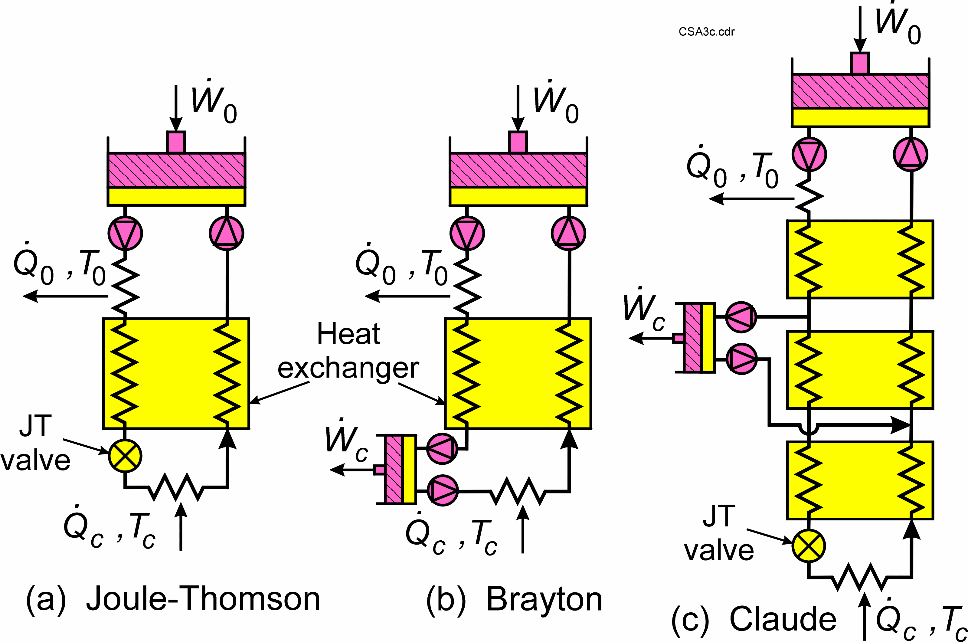
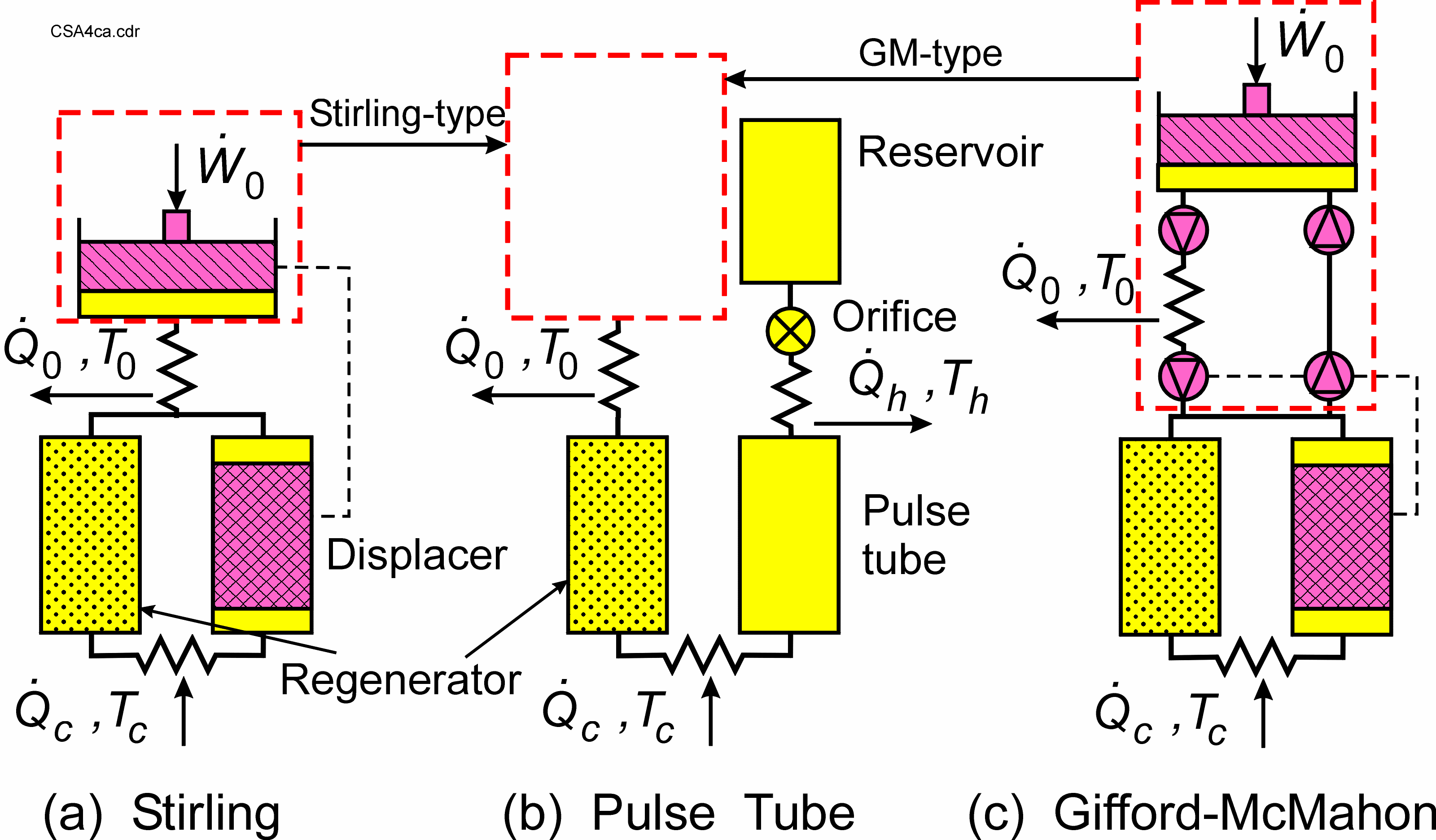
There are six commonly used cryocooler types, which are divided into two categories — recuperative cycles and regenerative cycles. Schematics of the three most common recuperative cycles are shown in Figure 1. Schematics of the most common regenerative cycles are shown in Figure 2.


Figure 2. Schematics of the most common regenerative cycles.
Recuperative Cycles
The recuperative cycles move the working fluid around a loop in one direction at fixed high and low pressures. The room-temperature compressor can either be a reciprocating-piston compressor with inlet and outlet valves or a unidirectional compressor without valves, such as a scroll or screw compressor. Efficient oil-removal equipment must be used in the high-pressure stream at room temperature to eliminate all traces of compressor oil from reaching the cold end and freezing. The heat exchanger for the recuperative cycles is known as a recuperator or recuperative heat exchanger. It has two separate flow channels—one for the high-pressure fluid and one for the low-pressure fluid. The low-temperature expansion can be with an orifice, capillary, or valve as in the Joule-Thomson (JT) cycle or with an expansion engine as in the Brayton cycle. The Claude cycle is a combination of the two in which an expansion engine is used for precooling and the JT expansion is used for the final expansion. Liquefaction often takes place in the final JT expansion.
he JT cycle normally uses a working fluid that is liquefied at the cold end, such as nitrogen for 77 K, hydrogen for 20 K, and helium for 4.2 K. For higher temperatures, mixed refrigerants of nitrogen and various hydrocarbons are often used to provide higher efficiencies.
Regenerative Cycles
The regenerative cycles, as shown in Figure 2, use oscillating flow and pressure with appropriate phase angles between the flow and pressure to achieve refrigeration at the cold end. Helium gas is almost always used as the working fluid. Maximum refrigeration occurs when flow and pressure are in phase near the cold end. The ideal phase angle is set by the phase of the displacer with respect to the piston in both the Stirling and Gifford-McMahon (GM) cycles. The displacer also recovers expansion work at the cold end and re-introduces it at the warm end to reduce the required input power from the compressor (pressure oscillator). Normally, there is no displacer in the pulse tube cryocooler, so the expansion work is lost unless a displacer is used at the warm end of the pulse tube. However, the lack of a displacer greatly reduces vibration at the cold tip. The flow impedance at the warm end of the pulse tube sets the phase between flow and pressure in the pulse tube cryocooler.
The oscillating pressure in regenerative cryocoolers can be generated with a valveless compressor (pressure oscillator), as shown in Figure 2 for the Stirling cycle, or with valves that switch the cold head between a low- and high-pressure source, as shown for the Gifford-McMahon (GM) cryocooler. In the latter case, a conventional compressor with inlet and outlet valves (or a scroll compressor) is used to generate the high- and low-pressure sources. These compressors are commercial oil-lubricated air conditioning or refrigeration compressors modified for use with helium gas, and they are used primarily for commercial applications of cryocoolers where low cost is very important. Oil removal equipment can be placed in the high-pressure line where there is no pressure oscillation. The valves greatly reduce the efficiency of the system, but allow the use of mass-produced refrigeration compressors. Pulse tube cryocoolers can use either source of pressure oscillations, as shown in Figure 2, and they are referred to as either Stirling-type or GM-type depending on the type of compressor used. The Stirling compressors must be oil-free because oil removal equipment cannot be placed in the oscillating pressure region.
The Stirling cycle typically operates with frequencies in the range of 30-60 Hz, whereas the displacer and second set of valves in the Gifford-McMahon cycle operate at 1-2 Hz to achieve longer lifetimes with rubbing parts. Average pressures are often in the range of 1.5-3 MPa (15-30 bar) with oscillating pressure amplitudes of 10-15 % of the average pressure. Stirling-type pulse tube cryocoolers typically operate at 30-60 Hz, whereas the GM-type operate at 1-2 Hz. Average pressures and pressure amplitudes for pulse tube cryocoolers are about the same as those for the Stirling and GM cryocoolers.
The heat exchanger in regenerative cryocoolers is called a regenerative heat exchanger or regenerator. It has only one flow channel in which the flow changes direction every half cycle. The incoming warm stream is precooled during the first half cycle by heat transfer to the regenerator matrix, typically a packed bed of fine screen or packed spheres. The matrix has a high heat capacity to store the heat for a half cycle. During the second half cycle heat is transferred from the matrix to the returning cold stream.
Cold-end temperatures achieved with regenerative cryocoolers vary from about 3 K up to 300 K, though temperatures below 150 K are most common. The lowest temperatures of about 3 K are possible with GM cryocoolers and GM-type pulse tube cryocoolers. The Stirling and Stirling-type pulse tube cryocoolers are mostly used for temperatures above 20 K. They have the highest efficiencies of all cryocoolers, which can be in the range of 10-20 % of Carnot at 80 K.
Applications
There are many common applications of cryocoolers. One of the most common is for the cooling of infrared sensors to temperatures of 80-150 K for use in military night vision equipment. The Stirling or Stirling-type pulse tube cryocoolers are most often used for such applications. Nitrogen or argon JT cryocoolers are used for the rapid cooldown of infrared sensors in missile guidance systems. The superconducting magnet coils in most magnetic resonance imaging (MRI) systems are usually kept at 4 K with GM cryocoolers that condense the boil-off from a bath of liquid helium. Many applications of superconducting electronics or power systems utilize the regenerative cryocoolers. Dozens of cryocoolers, mostly Stirling and Stirling-type pulse tube cryocoolers now fly in space aboard satellite for the cooling of infrared sensors. Some have operated continuously for over 10 years. Such cryocoolers use flexure or gas bearings to eliminate rubbing contact in the moving parts.
Further Reading
R. Radebaugh, “Cryocoolers: the state of the art and recent developments,” J. Phys.: Condens. Matter 21 (2009), 164219.
R. Radebaugh, “Development of the pulse tube refrigerator as an efficient and reliable cryocooler, Proc. Institute of Refrigeration (London) Vol. 96 (1999-2000), pp. 11-29.
R. Radebaugh, “Review of refrigeration methods,” in Handbook of Superconducting Materials, 2nd edition, D.A. Carwell and D. Larbalestier editors, Taylor and Francis Books (2020) to be published.
A.T.A.M. de Waele, “Basic operation of cryocoolers and related thermal machines,” J. Low Temp. Phys. 164 (2011) pp. 179-236.
Contact Information
- Ray Radebaugh (project leader, NIST Fellow emeritus); [email protected]; 303-497-3710.